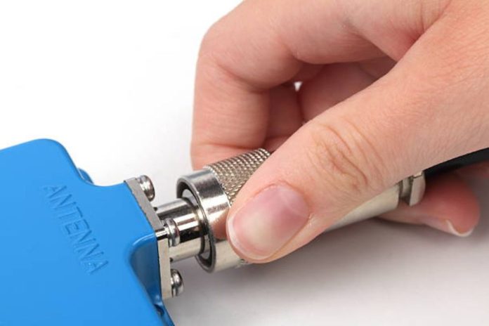
In the RF and microwave industries, many types of coaxial connectors are designed for specific uses and applications, are smaller, and operate at frequencies up to the GHz and millimeter wave ranges. An industry-accepted connector standard that is compatible with other RF/microwave components and can be used to interconnect coaxial modules within a system while maintaining the coaxial characteristics of the corresponding transmission line. There are many types of RF connectors with different classifications. How to choose the appropriate RF connector?
Types of RF connectors
According to the connection interface structure, it is divided into:
Threaded connection
Use series such as SMC, SMA, TNC, N, UHF, 7/16 and 4.1/9.5, suitable for test equipment, military and telecommunications equipment.
Bayonet Type
Use series such as BNC and MHV for reliable connection and quick plug-in, and are mostly used in test equipment and military equipment.
Push-in
It allows very fast coupling and separation, and its structural features are reliable. It is often used in small connectors, such as MCX and SMB series.
Push-in self-locking
Unique self-locking method, very reliable, usually on high-density small connectors, such as 1.0/2.3, 1.6/5.6 series, fast plugging and unplugging and reliable locking.
slide-in
Used in different DIN multi-terminal connectors, often used for connections on PCBs.
Classification by size:
Standard type
UHF, N, 7/16, 7mm
small
BNC, TNC
Ultra small
SMA, SMB, SMC, MCX, BMA, SAA, 3.5mm
miniature
SSMA, SSMB, MMCX, 2.4mm, K (2.92mm), 1.85mm, 1mm
Classified by frequency:
Audio: below 20KHz
- Video (Vidio): below 30MHz~500MHz
- Radio frequency (Radio): 500MHz ~300GHz
- Optical fiber (Fribre Optic): 167THz ~375THz
- Connectors used in the Radio band are called RF connectors.
Connectors used in the Radio band are called RF connectors.
Divided according to termination method:
- Connector MIL-C-39012(GJB681)
- Adapter MIL-A-55339(GJB680)
- Microstrip and stripline ML-C-83517 (GJB976)
Divided by function:
- General type (level 2)
- Precision type (level 0, level 1)
- Special type (irradiation resistance, high pressure resistance, waterproof, etc.)
- Multifunctional type (including filtering, phase modulation, mixing, attenuation, detection, limiting, etc.)
RF/microwave coaxial connectors come in several categories. As with coaxial cables, the cutoff frequency is a critical characteristic of any coaxial cable connector and represents the highest frequency at which the desired single TEM propagation mode can be maintained. The frequency range of any connector is limited by the propagation modes in the corresponding coaxial system. Millimeter wave coaxial connectors refer to coaxial connectors used for frequencies above 18 GHz.
Type N, BNC and TNC connectors
The 50-ohm N-type connector was developed in the 1940s and was originally used in military systems operating below 5 GHz. Type N connectors feature an internal gasket with an air gap between the center conductor and the outer conductor. Although subsequent improvements increased its performance to 18 GHz, even the latest designs will start to undergo propagation changes at around 20 GHz. That is, there will be unpredictable consequences when using this type of connector at frequencies of 20 GHz or higher. The 75 ohm N-type connector is widely used in the cable television industry.
BNC connectors are used for video and RF applications up to 2 GHz, using slotted outer conductors, and both male and female connectors are equipped with plastic dielectrics. At high frequencies above 4 GHz, slotting can emit signals up to about 10 GHz. Because the mating geometry of BNC connectors is compatible with N connectors, some BNC connectors can be temporarily mated with N-type connectors of corresponding polarity.
TNC connectors are a threaded version of BNC connectors. This version helps solve leakage and stability issues and allows use at frequencies up to 12 GHz and 18 GHz. TNC connectors are widely used for RF/antenna connections in cellular phones.
SMA and SMB push-fit connectors
The SMA (subminiature type A) connector uses a 4.2 mm diameter outer coaxial conductor filled with PTFE dielectric. Depending on the manufacturer, the upper limit frequency is 18~26 GHz. SMA connectors are sized to fit a 5/16-inch (12.7/40.6 cm) wrench and mate with 3.5mm and 2.92mm connectors.
The SMB (subminiature B/subminiature B) connector is a push-on connector, usually used in frequencies from 4 GHz to 12.4 GHz. As people require higher and higher frequencies, this type of connector has the problem of being too large and unable to provide the bandwidth required for high-frequency applications.
3.5mm and 2.92mm connectors
The two connectors using air media are not only compatible with each other but also with the SMA connector.
The 3.5mm connector can operate stably at frequencies within 26 GHz, while the 2.92mm connector has a maximum operating frequency of 40 GHz.
2.4mm and 1.85mm connectors
2.4mm and 1.85mm connectors are compatible with each other, but their design is not compatible with SMA, 3.5mm and 2.92mm connectors. This is because these two types of connectors are more precise and more expensive. If mated with lower precision connectors, they may cause irreparable damage.
1mm and 0.8mm connectors
Both connectors are suitable for millimeter wave analysis, supporting transmission and repeatable interconnect applications in the DC~110 GHz range.
Choose the right RF connector
How to choose the appropriate RF connector can be determined according to the actual application. If you choose purely based on performance, you can judge based on electrical performance indicators.
The main indicators of RF connectors are:
Impedance
Almost all RF connectors and cables are standardized to 50ohm impedance. The only exception is the cable TV connector for 75ohm TV systems. It is also important that the RF coaxial cable connector has a characteristic impedance that matches the cable.
VSWR (Voltage Standing Wave Ratio)
VSWR is an indicator commonly used by engineers to evaluate RF connectors. It is similar to impedance. Under normal circumstances, the VSWR is guaranteed to be less than 1.2 within the frequency range of interest. But it does not necessarily have to reach 1.2. Some of them meet the requirements if they are below 1.5 or 2. The lower the better, of course, and the cost will be correspondingly higher.
Frequency Range
The operating frequency range of RF connectors must be paid attention to in the high-frequency and high-speed fields. The frequency is divided into several grades, such as 1~6GHz, or 0~18GHz, 20GHz, 27GHz, 40GHz, 50GHz, 67GHz, 110GHz or even higher.
Insertion loss
Loss is a metric that all connectors pay attention to. It’s just that usually the loss of RF connectors is relatively small (if it is too large, it means there is a problem). Generally, within the frequency range of concern, it is within 0.1~0.5dB.
Return loss
For some engineers who work on digital circuits, VSWR is not so intuitive, so some use return loss to characterize it.
Number of times of use (plugging and unplugging)
The number of uses is generally considered to be the number of times a connector is plugged and unplugged before its performance changes.
Generally, the plug-and-pull times of RF connectors are 500 or 1,000 times, which also have higher requirements.
If you want to do some experiments in this area, you must do it under a specific torque/torque, otherwise it will be difficult to guarantee the number of uses. The connectors I have used generally do not reach this number.
It is estimated that they have been used 100 or 200 times.
The inner core is deformed because there is always the possibility of inserting it crookedly or twisting it too hard.
In addition to the above electrical properties of the connector, the mechanical properties of the connector (fixation of the central contact, mechanical strength of the connector, vibration, impact, etc.), environmental performance (climate category, sealing, salt spray) and connector Durability (mechanical durability, high temperature durability) are all considerations in choosing the right connector. In actual applications, you can choose your appropriate connector based on the above factors.


